

1. Remove screws from red plastic spacer but leave the spacer in place. The aluminum bracket may need to be removed to access the screws.
2. Center the table on the black base.
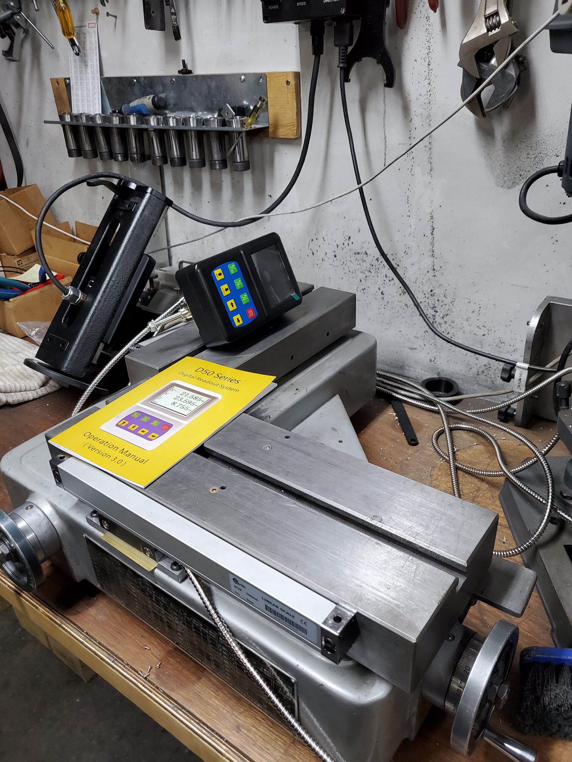
3. Center the linear scale on the table.
4. Center the read-head on the linear scale.
5. Mark the position of the two outer mounting slots on the aluminum read-head bracket. The slots can be exposed by sliding the linear scale to the left and right.
6. Drill and tap holes for the supplied 1/4-28 x 3/4″ button-head screws. Holes should be .625″ from the table face. Mount the aluminum bracket to the black base with 1/4-28 x 3/4″ button-head screws.
7. With the linear scale centered on the table and read-head, mark the position of the two outer slots on the linear scale. Ensure there is no gap between the linear scale, the red plastic spacer and the read-head.
8. Drill and tap holes for the supplied M6 x 1″ socket-head cap screws. Mount the linear scale to the table with M6 x 1″ socket-head cap screws.
9. Covers can be installed with two pieces of double-sided tape on the top of the linear scales on the ends. Plastic side pieces are installed with provided screws.
10. Routing cables can be done with provided clips, taking note that they must be installed on the side of the base, not the top.
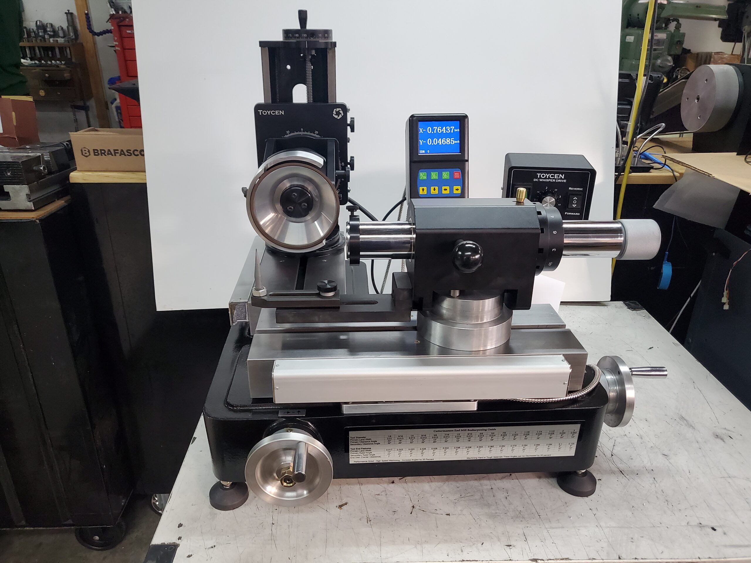
11. The digital read-out screen can be installed beside the control box with the provided black bracket and bolt/nut.